Complete CAM solution for Rhino + Grasshopper 

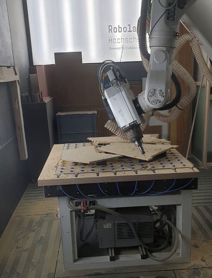
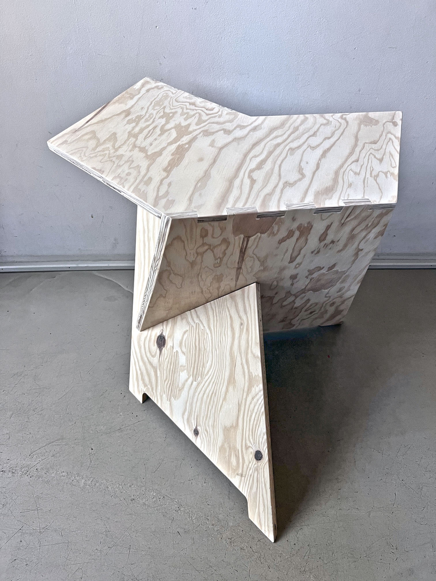
Woodbee is a compact CAM plugin for Grasshopper currently focusing on the milling objects from planar sheets. The tool can automatically detect different features in the input geometry and suggest suitable milling strategy based on the given tool and machine type (3 axis to 6 axis machines). Once the tool path is generated it can be simulated in Rhino viewport in real time. After a successful simulation, the tool path can be converted to GCODE or KUKA command using the specified postprocessors.

Robotic milling

With Woodbee plugin you are able to create robotic tool path from different milling strategies and simulate them using KUKAprc plugin.

Parametric Fabrication

Woodbee provides you with a fully integrated work flow for parametric fabrication inside Rhino+Grasshopper. 

Buy Woodbee

License Types

We offer various license types for Biber , catering to different needs and durations. Before choosing the most suitable license for your requirements, let us introduce you to the available options:

IMPORTANT NOTICE

Always download latest version of Woodbee.

Please remember that all licenses will not be renewed automatically. To continue using Woodbee beyond the license’s expiration date, users must renew their licenses before that time.

Additionally, we highly recommend considering the Professional License or licenses with longer durations, as we may introduce more features to the software in the future. Purchasing a longer-duration license ensures you have access to these new functionalities without incurring any additional costs.

Learn Woodbee

introduction to Woodbee plugin

Woodbee is a CAM plugin for Rhino+Grasshopper focusing on the milling from planar sheets. The plugin offers a very simple workflow to generate CNC or Robotic tool-paths. The parts in this video are generated using Biber plugin , al link to the webpage follows :

part1 : tool setup

in this video I create a drill and a tool holder in Woodbee . This tool will be used for rough-cut and fine-cut in later videos

part2 : Rough cut

In this video we use the tool which we have created in previous tutorial to generate a tool-path to perform the rough cut. With rough cut we remove the material with certain offset from the actual part. This is usually done with special tools which can move faster and with less vibration within the material. The result is a rough part which will be milled to the actual part in the next stage (fine-cut)

part3 : Fine cut

In this video we use a different tool to mill the details of the geometry from the rough part created in the previous tutorial. The fine cuts may include 3 different strategies, 2d , 5d and surface contouring.

part 4 : Feeds & Spindle

In this video you learn how to adjust the speed for different parts of the toolpath such as Rapid feed , Work feed, engage and retract feeds. Also how to set the spindle RPM.

part 5 : Contours & depth of Cut

In this video we use the operation modifier component to adjust the depth of cut for the 2d contouring operation. We can also adjust the contour offset and the starting point of the contours. In the depth of cut section we can add additional vertical (in depth) and horizontal (in plane) passes for better surface quality.

part 6 : Machining strategy

In this video we are going to see two different strategy to perform 2d contouring. Parallel passes and Helical contouring. We also can choose the milling direction (bidirectional, climb or conventional milling) . At the end the contours can be sorted by layer or by feature.
It is also possible to treat the external corners with an arc or a line move.

part 7 : Leads and safe moves

In this video you learn how to modify the engage and retract path by creating a transitional movement between the vertical move of the tool in free space and horizontal move inside the material. Creating these transitions helps to protect your tool and achieve better quality at the points in which tool enter or leaves the parts. We also look at options to control the safe plane ( the plane where the tool travels with rapid feed above the parts) and decide where the rapid feed should change to work feed.

part 8 : Links and Overlaps

Just like the settings in Link section which were controlling how the tool engages or retracts from the material in the vertical plane, the settings in the Lead section controls the engage and retract part of the tool path in horizontal plane. The entry and exit overlaps are also provided to extend the work path from the start or the end.

Exporting G-Code

In this video you can see how easily the Woodbee toolpath can be exported as G-Code for machining. If you wish to order the postprocessor for your machine feel free to contact us at info@parametriczoo.com

Woodbee to KUKAprc

A toolpath created by Woodbee plugin can be easily converted to KUKA commands. The commands can be then used to create a simulation.

Version Log

Version 1.0.5.0

Initial verion (this is a Beta version valid till 30/12/2022)

Woodbee forum
 
Notifications
Clear all

Woodbee forum

Discussion about Woodbee plugin and its post processors
Topic Title
Last Post
Views
Posts

zexus
By laker14
3 weeks ago
47
3

zexus

test

zexus, 4 weeks ago

By lumjer
4 weeks ago
34
7

Manfred Zalotec
By PARA
1 year ago
877
2

Share: